|
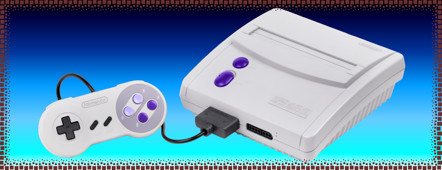
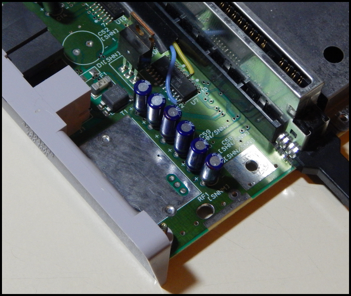
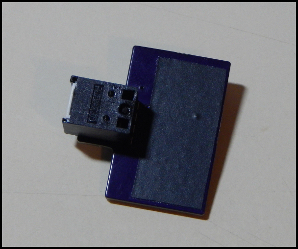
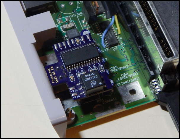
SNES DA RW Installation Guide for the 'Junior' SNES: The Junior SNES does not have an actual RF port hole, so cut-modding is required to install the board. My preferred output type for cut-modding is optical, though you can easily use coaxial and secure the board in your perferred location. Since this particular guide is for optical use, you'll need to solder the provided optical jack to your RW mod board. Remember to slip the pins through the terminal holes from the underside of the RW board (which labels the area as "mounting side"). For optical board placement, the spot where the RF box would have been (that Nintendo never used) is an excellent choice. See the image below where I have temporarily removed the heat sink for easier access to the area:
You can see there are a row of capacitors that border the RF box 'space' on the Junior's mainboard. The back end of the RW board will gently rest atop these caps. Now even though the RW's 'vias' are tented at the factory to protect against shorting on the bottom of the board, I always recommend lining the back of the mod board with a piece of electrical tape:
Just make sure you have already written down the pad assignments for your wiring!
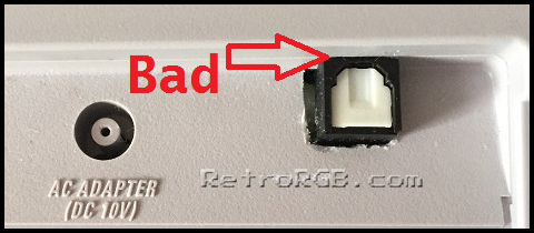
Next, you'll want to start carving out and shaping a square port hole for the optical jack to stick through. It's important NOT to carve the hole flush with the top edge of the back panel, because you won't be able to fit an optical cable into the jack. Here's an example courtesy of RetroRGB showing the lack of clearance on a bad port carving:
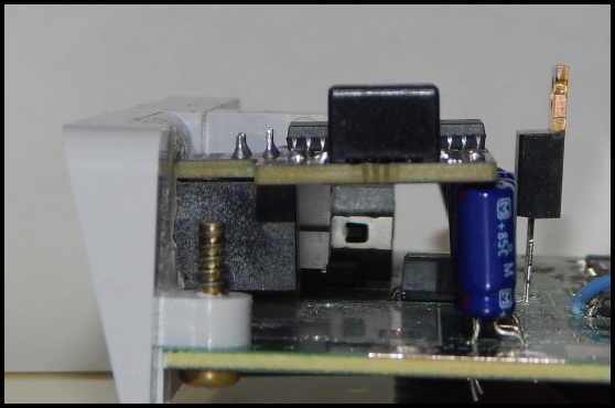
So you'll want a minimum of 3 millimeters of clearance from the top edge of your square port. On my port, I ended up with 3.5 millimeters, which worked out great. You can see from the positioning below that the 3.5 millimeter clearance kept the board close to level while sitting atop the caps:
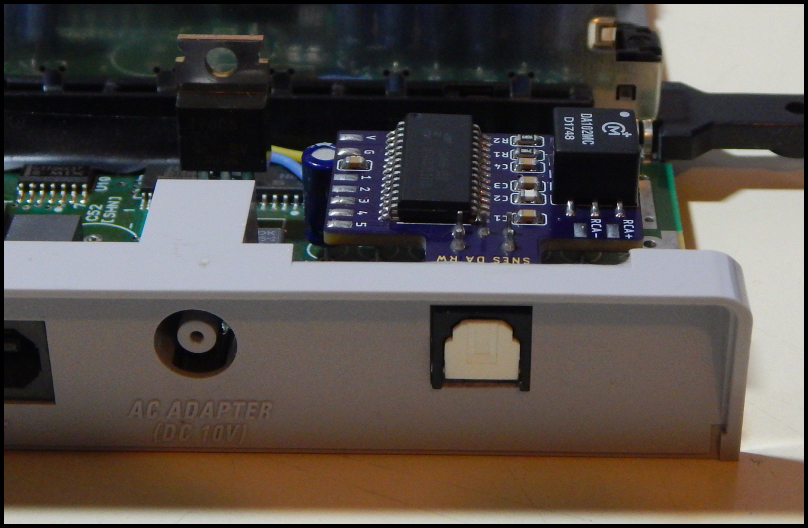
When shaping the port hole, the idea is to make it just big enough that the optical jack fits snugly. Use a cosmetic nail file to sand and shape the edges into a perfect square, stopping to check for proper alignment and fit with the optical jack. This is a labor of love and can be made to look proefessional in quality! Below is my own finished port hole fit for the mod board's optical jack positioning:
Once you're satisfied with the port hole and positioning of your mod board, apply some super glue around the optical jack where it fits into the port hole, then slide the jack through the port hole until it's sugly into position. The glue should now be left to set and dry, sealing the optical jack and mod board into play. Remember the board's back end should be sitting just atop those caps.
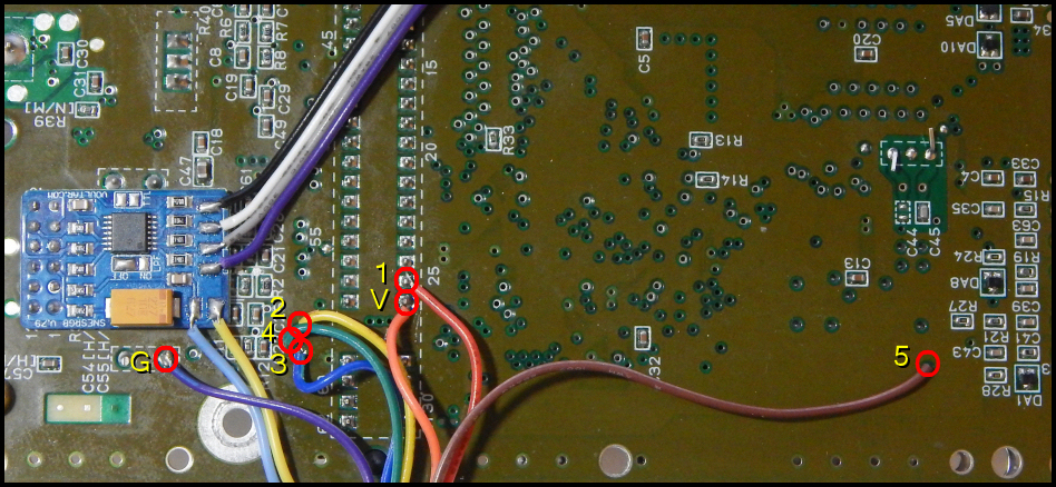
SNES Junior Wiring for the RW mod Board: I've provided a picture below that shows where each wire should be soldered to the underneath of the Junior main board. Some points are legs you can solder to, while others are vias you can solder to. Each point is designated with the corresponding number or letter on the pads of the RW board:
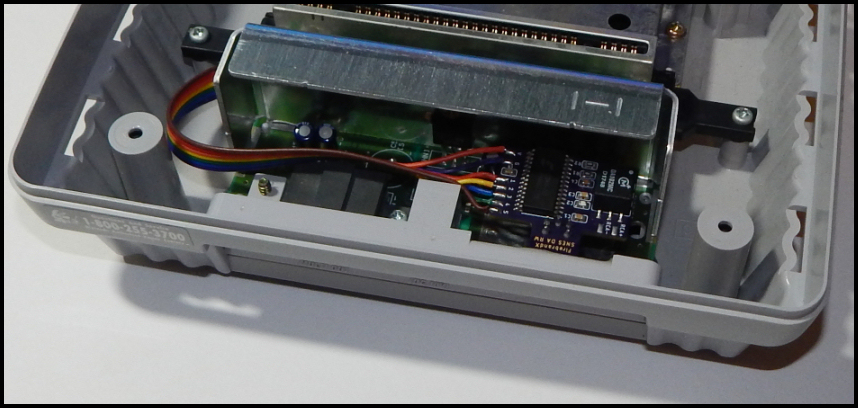
And here's a shot of the mod board wired in place on the Junior with the heat sink re-installed:
|