
Introduction:
The purpose of this web page is to serve as a detailed logical guide on extracting and transmitting digital audio from the original Sony Playstation via citrus3000psi's open source transmitter and Toslink PCB files from OSH Park. The example mod presented in this guide was applied to an SCPH-5501 revision console. Various revisions of the original Playstation will have different motherboard layouts, different DAC chips, and indeed the later revisions (SCPH-750X and beyond) are not compatible with this mod due to having the DAC integrated in the CD/DSP chip. For more specific information on your compatible Playstation revision, consult your preferred search engine on the location and type of DAC chip used. With reasonable deduction, you can figure out where and how to tap into the various digital signals needed to make this mod a reality on your own console.
The mod I promote involves a "no-cut" approach, meaning it can be done and then later completely removed with no damage to the console. I'll also show photos of citrus3000psi's cut mod, which will give an idea that, while it is externally more professional in aethetics, it's also a lot more time-consuming, difficult, and of course permanently damaging to the console's shell and internal structures.
|
Is It Worth Doing?
In a word: Absolutely! This is of course provided you have a means of receiving digital audio with your amplifier or capture device. Digital audio will almost always sound considerably more clean and devoid of background noise compared to analog audio. The Playstation is no different, and in fact sounds exceptional when transmitting digital audio from your games on the system. Provided below is my first recording test taken from my completed no-cut modified Playstation (music is from Tobal No.1):
PSX Digital Audio Mod Sound Test
And here is the finished mod with externally mounted Toslink optical jack used to make that recording:
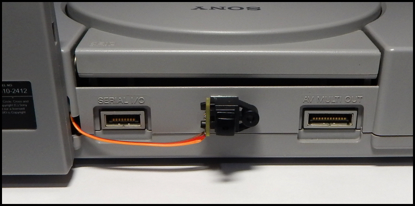
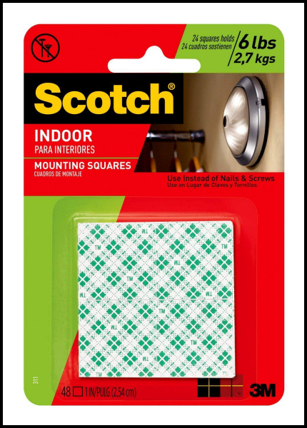
While it may not look very pretty, it makes use of Scotch mounting pads, which are strong and firmly hold objects in place. The cool thing about these pads is you can easily remove them by weakening the adhesive with a little WD-40 or even rubbing alcohol. So while the bond is strong, it isn't going to hurt anything with proper removal, and certainly is less messy than hot glue or superglue methods. You can buy these pads on Amazon, and I also include them in my own mod board kits on my web site.
|
|
So How Does It Work?
So Dan's (citrus3000psi) mod is actually two separate boards: The main transmitter board and the Toslink mounting board. Both are shown below in OSH Park preview images:
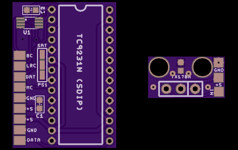
The idea is to tap into the I�S digital data signals that are normally sent to the Playstation's DAC for conversion into analog audio. The main transmitter board then processes the information into a positive phase pulse output, which in turn is sent to the powered Toslink jack for transmitting the signal via red LED through a fiber optic cable connected to your receiver/capture device. On Dan's board, you'll see the first 6 wire pads are inputs, and the next 3 down the bottom of the board are the output lines that connect to the Toslink board. This means we need to tap 4 digital signal sources in addition to ground and 5-volt power from the Playstation in order for this mod to work. Here are the details on the digital signals from the Playstation:
1.) "BC" = Bit Clock. Timing is 2.1168MHz (48 times the sample rate, or simply "48Fs").
2.) "LRC" = Left-Right Clock. This is what determines the sample rate of the digital audio, which for the Playstation is 44.1KHz.
3.) "DAT" = Serial Data. The actual sound data feed.
4.) "MC" = Master Clock. This signal is used to help synchronize processing. Sony opted for a more atypical MC timing rate of 16.9344MHz, or 384 times the sample rate (384Fs for short). The more popular master clock rate is 256Fs. Examples of MC rate being 256Fs are the Super NES and Sega Saturn (both of which can also be modded for digital audio output). Indeed you may have noticed the jumper pads on Dan's transmitter board, where one side sets 256Fs for Saturn timing, while the other side sets 384Fs for Playstation timing.
|
|
Why Use Toshiba?
It's important to note that there are 3 main chips on the market that are the most popular for hardware-based transmission of digital audio:
The Cirrus Logic CS8406.
The Texas Instruments DIT4096.
The Toshiba TC9231N.
Of the three, the Toshiba chip is no longer in production and you have to order it from 3rd party sellers on ebay or other online dealers that have old stock still on hand. So then why does Dan use it for his mod board? Well firstly, the Texas Instruments DIT4096 chip was known to have inteference issues when tested for this kind of mod. Then you have the Cirrus Logic CS8406 chip, which is an excellent transmission chip widely available in different package sizes. I in fact use the CS8406 in my Super NES digital audio mod board I offer for sale on this web site. The problem is the CS8406 is strangely missing a flag setting for 384Fs in hardware mode, yet it handles it just fine in software mode. This makes it much too complicated to implement for a basic digital audio mod, and we're back to having to use the discontinued Toshiba chip. I really think Cirrus Logic just goofed on the lack of 384Fs support in hardware mode. It has two different flag settings for 256Fs, and I'm betting one of those was intended to be for 384Fs.
With that said, lets take a look at the schematic for "Playstation mode" in Dan's transmitter board:
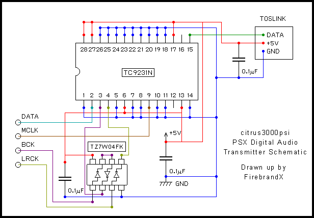
As you can see in the schematic, a small inverter chip is used to buffer and invert the "LRC" sample rate signal. Additionally, the "BC" signal is passed through the chip twice, flipping it back to original phase. I reached out to Dan to inquire about why this is done, as logically it shouldn't be required. He agreed that it probably could be skipped, but possibly it keeps the signal clean (i.e. buffered). He also informed me that this board actually was not his design. It originated on a long-since abandoned Japanese web site.
At any rate, take note of pin 7 in the schematic. This is the pin that informs the chip in hardware mode what the MC clock rate is coming in at. When the pin is tied to ground (bridged to pin 8), the chip is set to expect 384Fs. When it is tied to power (bridged to pin 6), the chip is set to expect 256Fs, thus explaining how the jumper pads work on Dan's board. Below are the OSH Park links to Dan's boards, where you can order them or download the files yourself:
Dans Digital Audio Transmitter Board
Dans Digital Audio Toslink Board (side pads)
|
|
Modding Time!
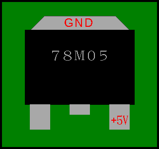
Right, let's get down to brass tacks and get this mod installed. First is to identify where to pull power and ground from. For the Playstation, you can easily pull both from the same part, which is a linear voltage regulator labeled "78M05". in my Sony SCPH-5501, it is located on the south end of the board near the controller ports. Simply solder some 26/28 AWG rainbow ribbon wire to the 5V power leg and another wire to the ground tab. Below is a diagram of the solder points on this part:
Now lets tackle the digital signals. For these, you can use kynar wire, which is thinner and stronger solid core material perfectly suited for digital signals. You'll need to locate the best spots to tap into each of the four digital signals we need to hook up to the transmitter board. Each Playstation revision is going to have a unique design, and often uses a different DAC chip. However, the same four signals will always be present somewhere on the board. The only exceptions to this are the later Playstation revisions of SCPH-750X and above, which again is due to the DAC being integrated into the DSP chip in order to save costs on manufacturing.
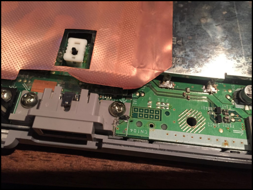
For my revision of SCPH-5501, I've highlight in color codes the lines we need to access and tap into:
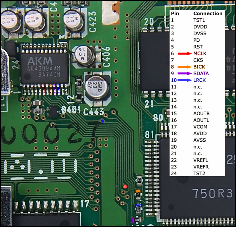
You can see there are easier access points to solder the kynar wires to near the bottom of the photo before the signals reach the legs of the DAC, which in this board revision is the AK4309AVM chip. Incidentally, this is the same DAC used in the original revision of the Playstation that became highly coveted by audiophiles as being a much superior DAC for analog audio output. You may have heard about this 2nd-hand, but pay no attention to it. Once stereo receivers began supporting digital audio inputs as the norm, DACs like this chip became pointless to chase after if you had a quality stereo amplifier with digital audio input jacks. Localized conversion of digital audio content is always going to sound superior to that of remote DAC conversion and transmission through RCA jacks. This is of course provided your equipment is even remotely decent. Digital audio is so common today that it's pretty much universally handled well by sound cards and amplifiers.
Once you tack the kynar lines, I like to bundle them together with some shrink-tubing. I use a WEP 858D hot air station set to 190 degrees C, with the smallest air nozzle and air flow set to 4 on the dial. After a couple of shrink tubes applied to the bundle of kynar wires, I route everything out the access port on the metal shielding as shown in the photo below:
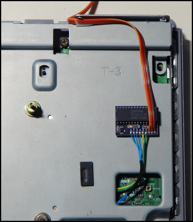
Note also in the photo how I have the power and ground lines wired up, and then the subsequent output lines soldered to the last three pads going out the top of the back of the console. I used a couple of trimmed pieces of scotch mounting pad to secure the output lines, and indeed the transmitter board itself is mounted to the metal shield with a Scotch pad as well. Can you tell I love using Scotch mounting pads? :-P
|
|
Summary:
Well that's really all there is to it! The only thing to pay special attention to at this point is noting the order of ground, data, and 5v pads on the Toslink jack board. They are a different order than on the transmitter board, and if you don't notice this, you'll end up shorting power to ground on the playstation motherboard. I 'tested' what happens when you short these lines, and it simply doesn't allow the motherboard to function (at least on the SCPH-5501). Getting the power and ground lines unshorted restores full functionaility of the motherboard. So just make sure you get this right and there won't be any problems.
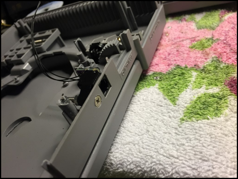
One other minor thing to be mindful of is when you reassemble the Playstation. Watch that gap in the serial out port and make sure you don't pinch the wires. Make sure they are cleared of being pinched and then just screw the case back together. Then enjoy your digital audio in all its pristine glory!
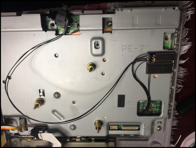
If you don't particularly care about the "no-cut" mod movement and don't mind hacking into your Playstation, below are pics of Dan's own internal install work. It's quite a bit more of an ordeal, but it makes for a nice clean look externally:
|
|
|