|
NESRGB Firmware Flashing Guide |
|
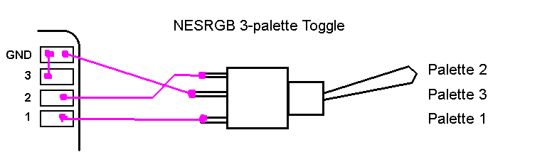
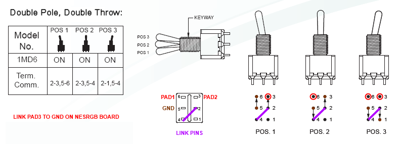
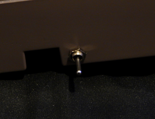
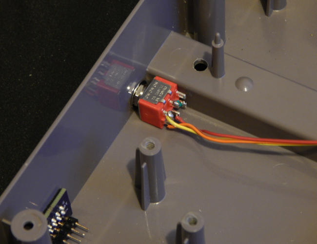
Please note that Tim's NESRGB palette toggle switch diagrams have palette #3 in the middle position of a single pole double throw switch, which has lead to likely the majority of NESRGB installations having this setup. Here's a visual diagram showing how the palette toggle switch is wired on Tim's instructions: However, "Link83" on the shmups forums came up with a fix for this using DPDT switches. Pad #3 is left shorted to ground on the NESRGB board, and then Ground, Pad #1, and Pad #2 are wired up to the switch as below: I've replaced my own NESRGB toggle switch with the 1MD6 model listed in the image above, and wired it up for palette #2 to take the middle position. It works great, though I found the switch was too long to use the same location the original switch used. Instead, I found a more spacious location that also allowed me to set the switch flush against two sides of the plastic housing. This keeps the switch perfectly horizontal and prevents incidental rotation. Here are some photos of my finished switch replacement job: NESRGB DPDT Toggle Switch: 1MD6 DPDT Toggle Switch Installing Palettes onto the NESRGB Board: Updating the NESRGB board with these palettes requires a rev. C Altera USB Blaster. These are dirt-cheap and can be purchased on ebay for about $6.00. Be sure to get one that includes the 10-pin ribbon cable as well as the USB-to-miniUSB cord. Next, you will need the NESRGB Firmware update files Tim created for these palettes. PLEASE NOTE: We now have firmware files for the new NESRGB revision 2 boards. These files are NOT compatible with the old 1.X NESRGB boards:
NESRGB Firmware Depository (April 16th, 2022): Download
Now you will need to install the Quartus II Programmer software from Tim's link here:
Once you have the Altera Blaster on hand, you will likely need to install the Altera Blaster driver by following the directions below:
In order to update the firmware on the NESRGB board, the board itself must already be installed in the Nintendo. This is because the board needs to be powered by the Nintendo during firmware updating procedures. When I first updated mine, I removed the housing, shroud, and cartridge interface from the Nintendo, and then lifted the main board from the bottom housing so I could flip it over and move the bottom shroud to the side. This gave me direct access to the NESRGB board while still being able to plug the power cord into the Nintendo.
UPDATE:
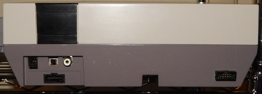
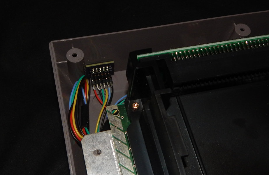
I later received help from Ste Kulov of HDRetrovision in the form of a custom PCB jtag adapter he designed for my needs. I've since modded my NES with a back access port using this adapter, and it allows me to update the NESRGB firmware by simply plugging the Altera ribbon cable directly into it without having to disassemble the NES. Here are some pics of the mod work and adapter board in place:
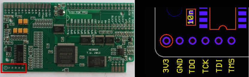
You can order the boards from OSH Park here: OSH Park NESRGB JTAG Adapter Board You will need one of these ribbon sockets: 10-pin Ribbon Socket And a row of male pin headers like these: 6-pin square posts Now that will at least get you started if you've got experience soldering. I went a step further and used a row of round slender pin headers, and then soldered the jtag wires to a corresponding row of female IC headers to slip onto those pins (as you can see in the internal image of my adapter port mod). This makes it so I can disconnect the wires from the adapter port without having to de-solder anything. Now if you prefer not modding the plastic housing of your NES, you can simply use the square-pin adapter assembly I linked to and hook it into the jtag holes of the NESRGB board directly whenever you need to flash the firmware. Details on the NESRGB board's jtag interface are shown below in the stripped wire method of updating the Firmware: Stripped wire method: You'll need to strip the ribbon cable that came with your Altera Blaster down to six individual wires. The red coating on the first wire corresponds to pin #1 on the Altera Blaster, and each wire after that corresponds to the next pin (i.e. the 2nd wire goes to pin #2, the 3rd wire goes to pin #3, and so on). The wires you want are 1, 2, 3, 4, 5, and 9. These will be hooked into the 6 terminal holes on the NESRGB board as indicated below:
Wire #4 goes into the "3V3" terminal. Wire #2 goes into the "GND" terminal. Wire #3 goes into the "TDO" terminal. Wire #1 goes into the "TCK" terminal. Wire #9 goes into the "TDI" terminal. Wire #5 goes into the "TMS" terminal.
Make absolutely certain you have the correct wires hooked into the correct terminals. I leave it to you to decide if you want to solder them or make a temporary interface (which is how I handled it). For reference, below is the Blaster pinout diagram:
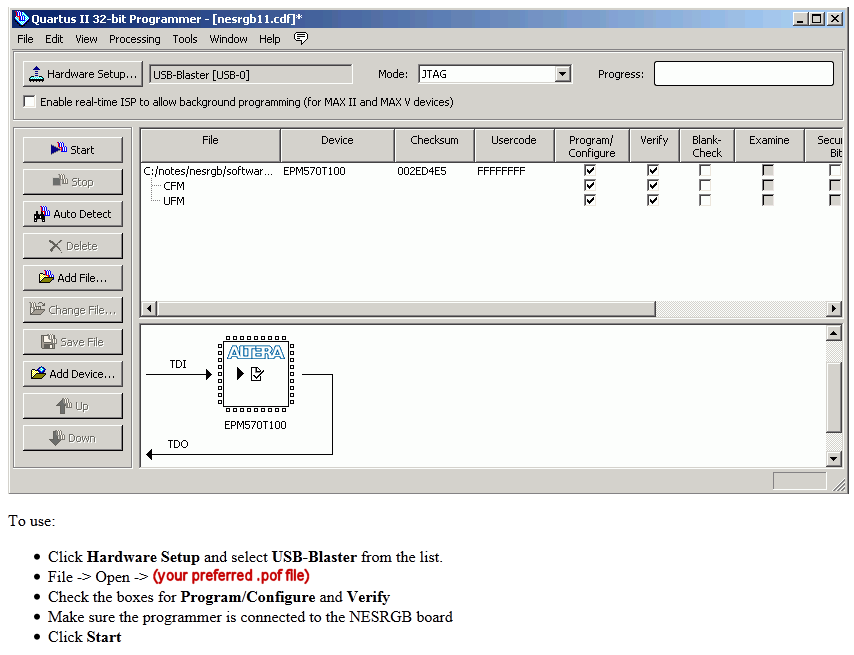
Once you have everything hooked up, power on the Nintendo and plug the USB cord-side of the Altera Blaster into your PC. Then run the Quartus II 13.1 Programmer and follow the steps below:
If everything was done properly, you should see the progress bar fill with green as the programmer updates the NESRGB board. Wait until it finishes, then close the program (don't bother saving when prompted), turn the Nintendo's power off, and unhook the Altera from your PC and Nintendo.
|