|
M1 Mini Mega Installation Guide: Note:
This board will be fully compatible with all Sega Genesis/Mega Drive model 1 revisions from VA0 to VA6.8. Effectively covering all YM2612-based model 1 consoles. Revision VA7 of the model 1 (the last revision Sega made before releasing the model 2) uses an ASIC 3438 design that is not compatible with this board.
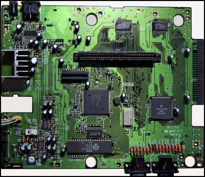
Below is a photograph of the model 1 VA7 revision motherboard that is NOT compatible with the M1 Mini Mega:
Step 1: Locating the Audio Pre-Amp Capacitors
Due to the 'mount anywhere' design of my bypass amp board for the Genesis/Mega Drive model 1 console, there are a number of different ways of installing the board. I provide my personal favorite method of stereo RCA jack output using the space the RF box takes up in the console (requires removing the RF box with desoldering equipment and flush cutters). The ports for the RF box provide a nice location to install the RCA panel mount jacks without needing to cut new holes into the console. Of course, you do not have to use the RCA jacks at all, and can instead use the stock headphone jack at the front of the console for output. I'll provide details of that installation method as well.
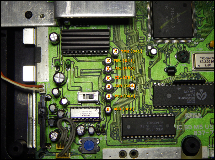
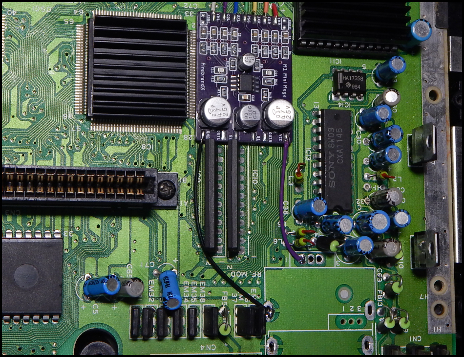
In the photo below, I've labeled the capacitors we need to remove in order to allow the M1 Mini Mega to take over operation of the pre-amp circuitry. This layout of capacitors is the same arrangement you'll find in all YM2612-based model 1 Genesis/Mega Drive consoles:
Step 2: Determining Soldering Points for Each Input Signal
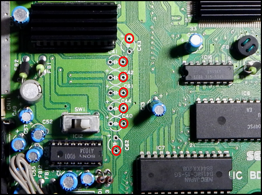
Whether you use a spring-loaded solder-sucker, desoldering gun, blade-tip iron to heat the legs, or just simply cutting the caps off the board with flush cutters, the key access points we need to solder to are circled in red below:
It's important that we ONLY tap into the positive side of the YML and YMR through-holes, while the rest of the through-holes require tapping the negative side. This maintains the original DC bias of the console, and thus, reproducing it on the M1 Mini Mega board itself. Step 3: Mounting the M1 Mini Mega Board & Wiring the Input Pads
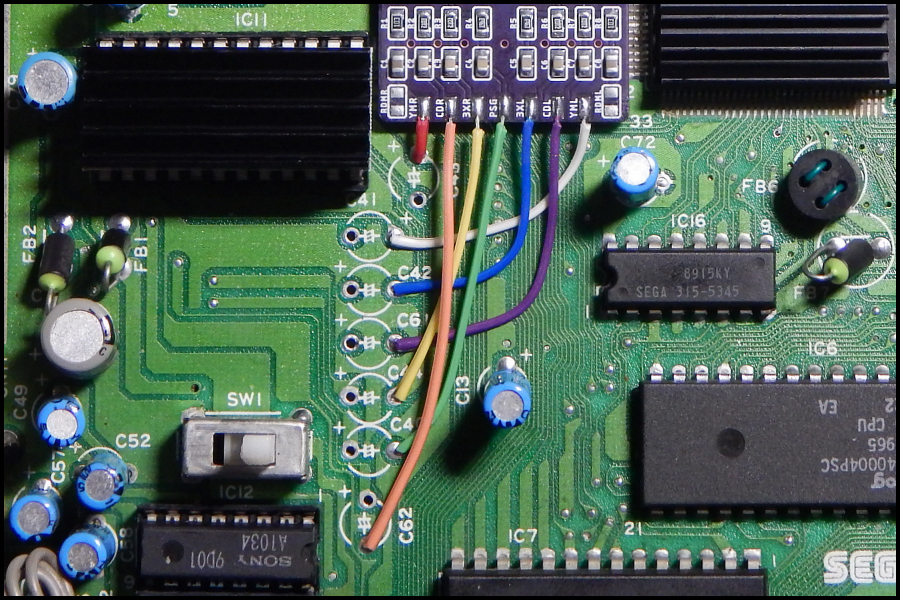
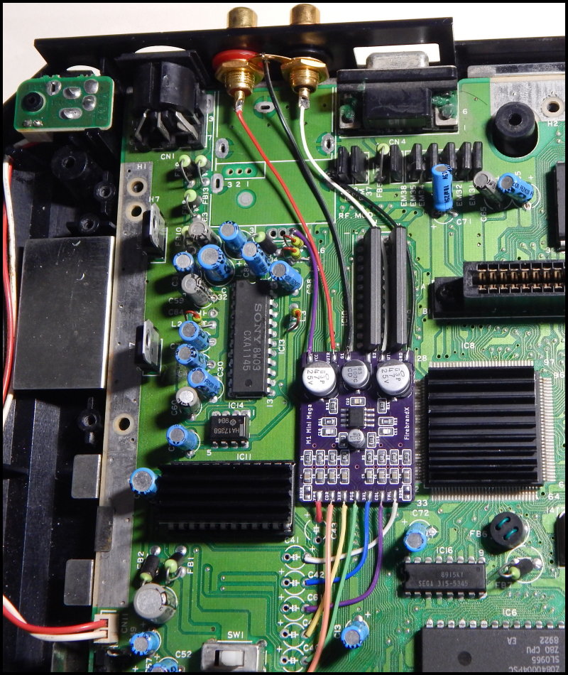
My personal favorite location to mount the M1 Mini Mega is in between the VDP chip and YM2612 chip such that the input pads of the board are just above the previously removed audio pre-amp capacitors. Simply peel the scotch mounting pad's cover off and plant the board into place. Then it's a simple matter of soldering the lines from each access point to the input pads of the M1 Mini Mega. I've used rainbow wire to show how each line connects to each tap point:
Step 4: Sourcing Power and Ground Tap Points
I like to use the power supply via meant for the RF box in order to supply +5V to the M1 Mini Mega board. The various slots for mounting the RF box are all grounded, and provide plenty of tap points for providing ground to the M1 Mini Mega board as well. In the photo below, I've wired up power and ground from these points to the proper pads on the M1 Mini Mega:
Step 5: Hooking up the Stereo Panel Mount RCA Jacks
Installation of the RCA Jacks is a little tricky. First and foremost, you'll want to fill the 'solder cups' for each jack with solder and solder wires to them with a few inches in length. Do this BEFORE attempting to install the jacks in the RF port holes. You'll then need to remove the Genesis motherboard from the bottom shell to install the jacks more easily.
The RF box channel selector port may be a hair too tight for the RCA jack to fit. In this case, you can take a hobby knife and shave a litte bit of the plastic in a crescent shape on the top and bottom edges of the channel selector port to allow the RCA jack to screw into place.
Once you've gotten them installed, rotate the ground rings such that their tabs are joined together. You can bend them a little outward from the back of the Genesis shell and tack-solder them together. After this is done, then it's just a matter of putting the Genesis motherboard back into the bottom shell and soldering the output and ground wires in place. Note that it can be a little tricky putting the Genesis motherboard back into place due to the RCA jacks, but you can tilt the board to slip underneath them and settle it into place. As I said, this can be a little tricky, but it's not terribly difficult to get the hang of. Below are pics of the RCA panel mount jacks installed and wired to ground and the M1 Mini Mega:
Once the install is completed like in the picture above, put the heat shield back onto the motherboard and voltage regulators. Note that you won't be able to re-secure the silver screws that go underneath the board, so I just screw them in on top to keep them safe from getting lost. All of the other screws can be put back in as normal, so the heat sink is tightly connected to the ground plane of the motherboard anyway. Step 6: Boot the Console and Play Some Genesis Music!
So just how awesome does it sound? Here's a link to an actual recording from the M1 VA2 installation shown in the previous step:
M1 VA2 Sega Genesis with M1 Mini Mega Installed - Thunder Force III - Venus Fire
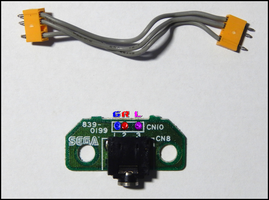
Stock Headphone Jack Installation Method: If you already use the RF box space for something else, or just don't want to remove the RF box, you can use the stock headphone jack by desoldering the existing lines that hook it up to the stock Genesis/MD amplifer chip. Highlighted below are the Ground, Right, and Left access points of the headphone jack's daughterboard:
Simply wire the outputs of the M1 Mini Mega to those ports and PRESTO! Crystal clear sound from the headphone jack for your RGB cables that use a mini-headphone jack breakout hookup. You can also source ground and power from a number of places in that same area of the motherboard where the headphone jack sits on top of as well. Use a multimeter in continuity mode to find your preferred source locations.
|