|
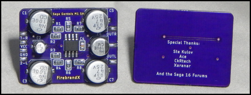
Sega Genesis M1 SA Example Installation Guide: Note:
Due to compatibility issues with revisions VA5 through VA7 boards of the model 1 Genesis/MD console, as well as input cap charge time delay on cold-booted Genesis consoles, this mod board is no longer sold nor supported on my site. These instructions are provided for those that already have the board.
My new board called the "M1 Mini Mega" will be fully compatible with all model 1 revisions from VA0 to VA6.8, and will not have cap charge time delay on cold-booted Genesis consoles. Look for these new boards to be sold on my web site soon!
Step 1:
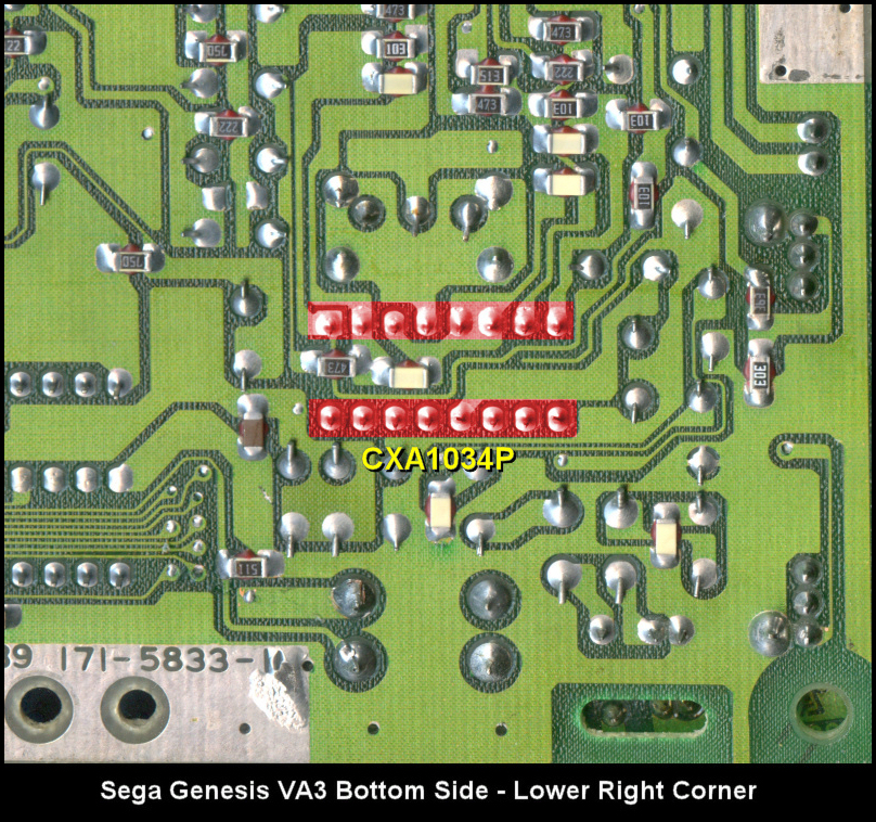
Due to the 'mount anywhere' design of my bypass amp board for the Genesis/Mega Drive model 1 console, there are a number of different ways of installing the board. I provide my personal favorite method of using the space the RF box takes up in the console (requires removing the RF box with desoldering equipment and flush cutters). However you decide to install the bypass mod board, you'll still need to be able to desolder and remove the CXA1034P WITHOUT damaging it. This means you need typical modding/desoldering experience with removing through-hole IC's.
In the photo below, I've highlighted in red the pins of the CXA1034P. These need to be desoldered properly to remove the chip from the Genesis/Mega Drive. I personally use a desoldering gun. Other people have become proficient at using spring-loaded 'solder suckers' and a hot iron. Jason at Gametech-US has many youtube channels of him doing this method, while Voultar has videos of the desoldering gun method also on Youtube.
Step 2:
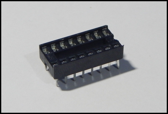
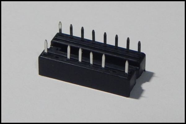
Now take the provided dual wipe socket that has ALL the pins intact and install it where the CXA1034P used to reside. Be sure the 'notch' of the dual wipe socket is facing in the correct direction as stenciled on the Genesis/Mega Drive board. This will provide a nice socket to plug the chip back into should you decide to restore original stock functionality of the model 1 Genesis/Mega Drive:
Step 3:
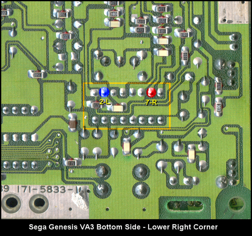
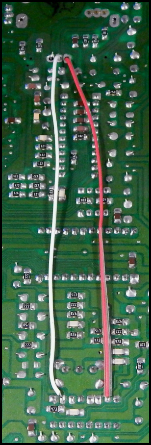
With the dual wipe socket properly soldered in place, we're going to tack one-foot-long wires to pins 2 and 7 (left and right inputs that normally go into the CXA1034P) as highlighted in the photo below:
I then route these wires through the two RIGHTMOST 'via' holes as shown in the image below:
Step 4:
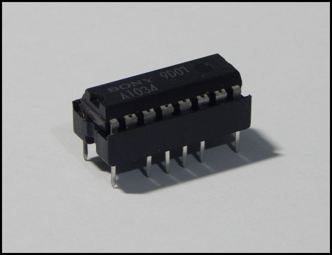
Now take the other dual wipe socket provided in the kit that has pins 2 and 7 already removed and install the CXA1034P into it, taking care once again to make SURE the 'notches' on the side line up:
And then carefully install the socket (again with the notches in the correct direction) into the dual wipe you installed on the Genesis/Mega Drive main board. Remember that the missing pins should be on the topside of the socket when you insert it into the existing socket. The reasons I have these steps included in this mod are 2-fold: 1.) It provides a safe storage location for the CXA1034P in case you ever want to go back to stock headphone output. 2.) The CXA1034P actually provides its own decoupling noise reduction, even though we're preventing pins 2 and 7 from connecting to it. I found this is important for maximum quality results:
Step 5:
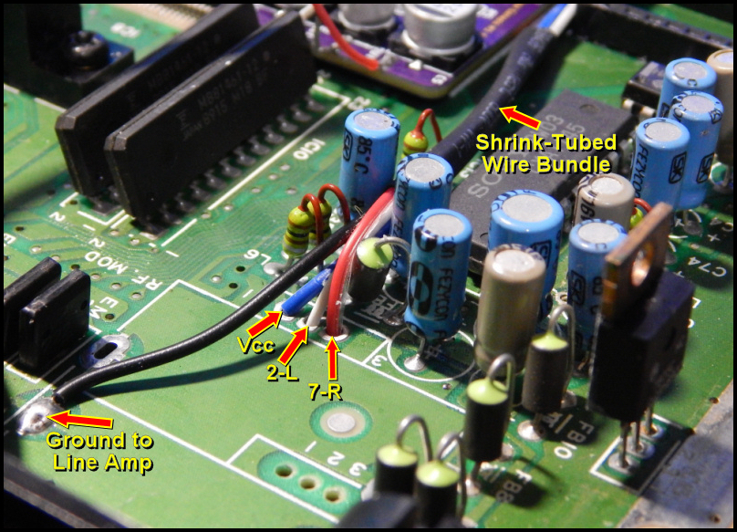
So now you should have several inches of wire coming out of those two 'via' holes in the RF box space. These provide left and right audio, but we still need to provide ground and power lines for the mod board to function. In the image below, I've highlighted the sources I like to use. The 3rd 'via' hole next to the two wires we fed through the board is a source of Vcc to pull from, and you can also see there are several spots in the RF space to pull ground from (though the image arrow only points to the one I chose to use):
I tack-solder about 6 inches of line to the Vcc via and the Ground via, then I bundle them with the left and right channel lines using shrink tubing (as seen in the image). I used a W.E.P 858D hot air station set no higher than 200 degrees to shrink the tubing around the bundle.
Step 6:
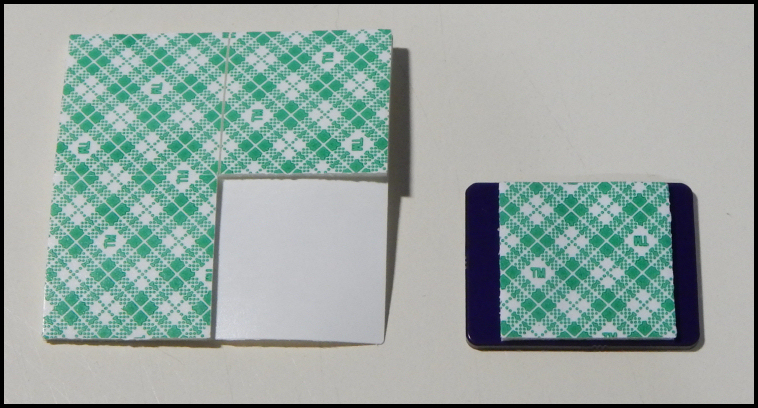
Now of course we need to use the Scotch mounting pad to prepare the bypass mod board for mounting in the console. I start by peeling the white sticker side and affixing the pad to the BOTTOM of the mod board as depicted below (note the board shown in the photo is an unpopulated blank, but you get the idea):
Step 7:
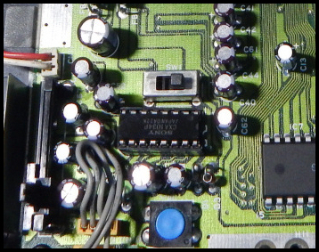
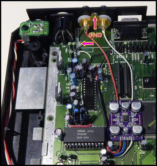
In the final image, you can see I firmly planted the mod board between the video encoder and VDP chips. Then I stripped the wires to fit neatly onto the pad assignments and soldered them in place.
You can also see how I used the RF box port holes to install the RCA jacks, using the plastic washers to hold them in place (this can be a little tricky, but they are just big enough to do the job). Then it was a simple matter of soldering the left and right channel wires from the jacks to the output pads on the mod board. I also chose not to use the output ground pad on the middle top of the mod board, since ground was readily available in the RF box space area (arrows show where my ground line was soldered).
Note: It's a good idea to pre-solder the positive input 'cups' of the RCA jacks before securing them to the plastic of the console. This is because the jacks get pretty hot when filling those cups with solder and installing wires, so you don't want to stress the plastic casing of your console with too much heat.
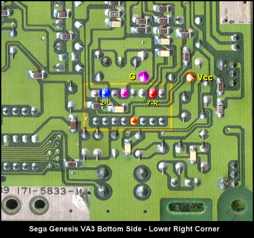
A Word About Alternate Installation Methods: If you already use the RF box space for something else, or just don't want to remove the RF box, you don't have to pull power and ground from the sources I did, nor do you have to route the lines through the RF 'via' holes. In fact, all sources can be pulled from the pins of the dual wipe socket for the CXA1034P. I've provided below the highlights for all sources needed for the bypass mod board if you want to pull everything from the same location:
|