|
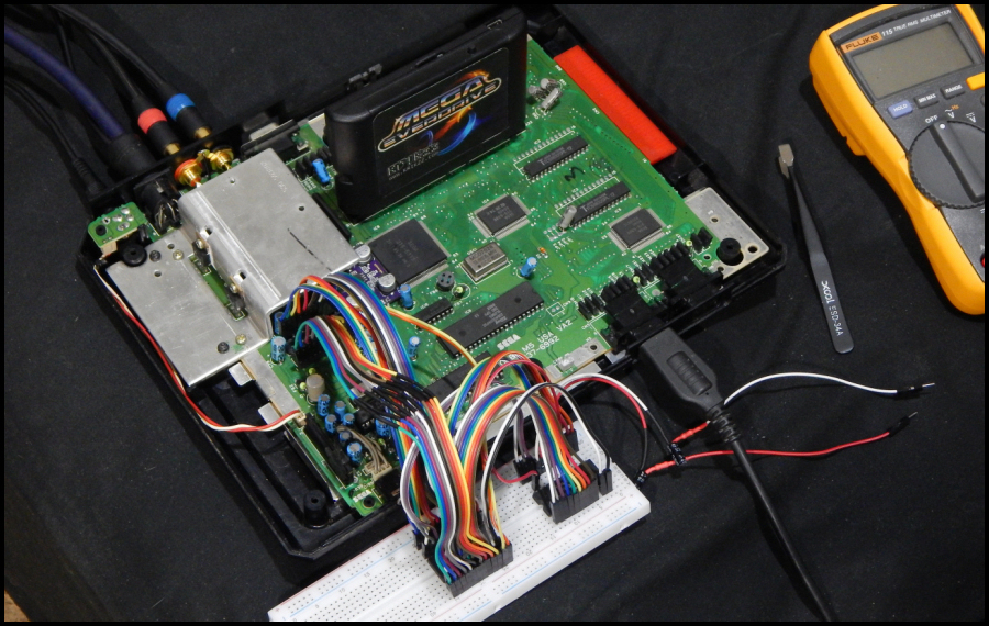
Model 1 Genesis/MD YM2612 and the Ultimate Audio Modification Setup: My focus the past few months has been on making a couple of audio modification boards for the model 1 Sega Genesis revisions that use a discrete YM2612 sound chip. One of the boards is a crystal clear 'line amp' bypass board designed to give superior sound to that of the stock headphone jack output, and the other mod is a dual toggle board that I call the "M1 Double Mega", which allows for an optional discrete YM3438 playback of the Genesis sound and music at the flick of a toggle switch. This is a 4-layer design PCB that breaks out the original "piggyback" mod such that no pins need to be bent or clipped on either YM sound chip. The schematic for that piggyback mod is floating around the Internet, but has a typo in addition to 'unvetted' series resistance on the discrete 3438 MOR and MOL outputs. The original pioneer of that mod (Michael MacEachern) meant for the series resistance to be 2.2K Ohms, but the online schematic just showed 2.2 Ohms. That's the typo. The 'unvetted' part was the value of 2.2K he arrived at, which was effectively just enough to get it working without distortion on most games for the M1 Genesis with YM2612 chips. When designing the breakout board, I started testing the outputs with very loud and very deep bass tracks, as well as comparing relative loudness of the PSG channel. Ultimately, the closest balanced value I arrived at ended up being 4.7K. This was co-verified by 'Crossbow' on the Sega 16 forums. Here's the ugly wire octopus I started off with in order to test the theory of actually making a working prototype PCB:
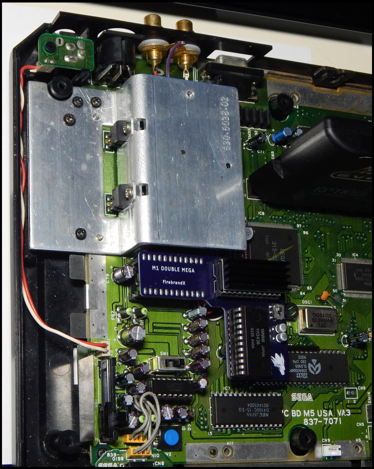
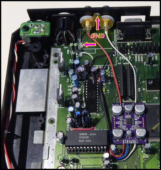
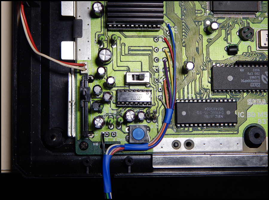
That ugly mess actually worked great for refining the resistor values and testing the viability of an actual toggle board for live-switching from either the discrete 2612 or the discrete 3438 audio chips. Below is a working prototype installed in my M1 VA3 Genesis console, which itself has been fully recapped, new 78S05 regulators installed, pre-amp filtering caps changed to 4700pF (to match the VA2 revision Genesis's LPF), and powered by a 9V 2A switching PSU in addition to my original Line Amp mod board installed & sitting to the left of the VDP chip:
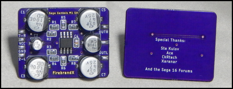
The Woes of the Original "Line Amp" Bypass Mod Board: At any rate, my original "Line Amp" bypass board relied upon the pre-amp mixing circuit of the M1 Genesis, with the trick of removing the 1034P amp and installing a dual wipe socket in its place. Then a 2nd dual wipe socket was stacked on top of that with pins 2 and 7 removed, such that the 1034P's input pins would not connect to the Genesis mobo. Here's a picture of the mod board as originally designed, followed by my own typical installation layout (note that you can also see the original 3438 'piggyback' mod in the 2nd picture):
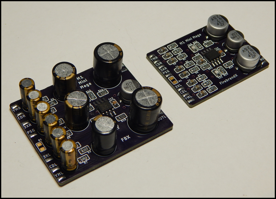
This concept worked great and gave fantastic unfiltered, crystal-clear audio with my Line Amp board on VA2 and VA3 consoles. Now where the problems started coming in were in revision changes. I believe starting in VA5 through VA6.8, something changed in the pre-amp mixing circuit to where users were sending me reports that the mod board wasn't working at all with the 2 and 7 pin isolation trick. Additionally, it was discovered that my input caps were causing 'steady state delay' on cold-booted Genesis consoles. I never caught this in R&D because I was using an X7 Mega Everdrive to test game audio. So what would happen is that by the time I selected a game to load from the library, the caps would fully charge to steady state, and the game audio would work just fine as soon as I loaded the game. As it turns out though, a physical game cart would boot right away, and the input caps wouldn't have charged up in time, causing the first 8 to 12 seconds of audio to be muted, and then the audio would crackle-fade in. With these issues of compatibility and steady state delays, I realized my approach was simply inferior to the Mega Amp method of bypassing the pre-amp circuity and including it on the mod board directly... Enter the "M1 Mini Mega":
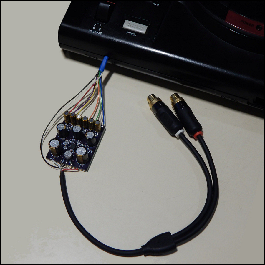
As you can see in the above image, I decided to make two different prototype versions of the "M1 Mini Mega". On the left is an electrolytic capacitor design that makes use of the finest audio caps Nichicon has on the market. On the right is a ceramic 0805 input capacitor design using X7R dielectrics. The idea here was to determine if using ceramic capacitors was causing distortion or other audio issues that one could detect with their own ears or even via wave form analysis. Some "Mega Amp" boards have been produced for public use that went with ceramic caps on the inputs, including one by a well-respected electrical engineer. I decided to conduct a single-blind study by rigging up a wiring harness out of the Genesis console to the mod board and then record tracks from both the electrolytic and ceramic versions of the board. Twitter users then downloaded the tracks and were asked to vote on which one sounded 'better' without knowing which one was which. Here are pics of the wiring harness and electrolytic version hooked up as an example of the ouput rig:
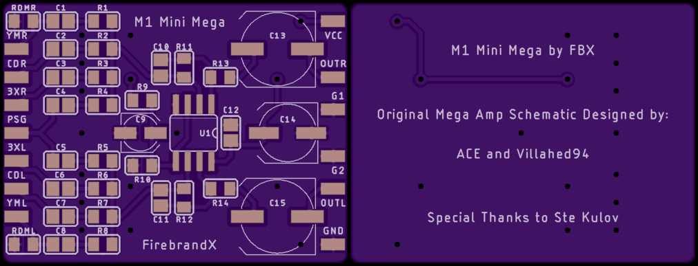
Results from that study showed the tracks were practically indistinguishable from each other. One participant confessed he was completely inconsistant on his choices after reviewing the study results. The only inference that actually could be made from the study as far as audio quality goes came from the choice of output capacitors. The "Muse" UKZ 47uF Nichicons gave a very SLIGHLTY cleaner tonal quality, while the UUX surface mount 47uF Nichicons gave a very SLIGHT increase of bass presense. For most participants, these slight differences could not be consistently detected. Below is the text file of the study findings: Ceramic versus Electrolytic Blind Study Results And of course I would be remiss if I didn't offer the readers of this article a few sample track recordings to listen for themselves (includes stock headphone recordings for reference to the original sound output): M1 Mini Mega Test Recordings Combining the M1 Mini Mega with the M1 Double Mega: On my M1 Double Mega board, I've set it up to where the toggle switch outputs to red and white wires (28 AWG multi-strand ribbon type). The user will be able to take those lines and hook them up directly to the new M1 Mini Mega board I am working on, as it will provide the required 2.2k pulldown resistors for those lines normally found on the Genesis board itself. Below is the preview of the OSH Park M1 Mini Mega board I've submitted for fabrication:
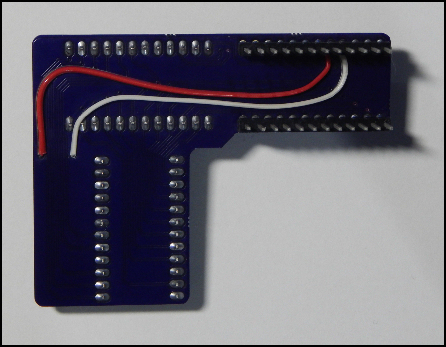
Obviously I want both boards to be completely independent of each other, allowing modders to use one or both boards as needed/wanted. In the case of the modder not being interested in the M1 Double Mega, the "RDML" and "RDMR" resistor locations will be left unpopulated. If the modder wants only the M1 Double Mega and not the M1 Mini Mega, then the red and white wires will be soldered directly to the board-to-board posts of the Double Mega, as seen in the example prototype below:
So this Mega Amp approach of bypassing the entire pre-amp mixing circuit is superior in concept in that it avoids compatibility issues as well as steady-state cap charge time issues. However, the established mixing circuit of the Mega Amp 2.0 is a little too loud for use with the M1 Double Mega board. Just using stock YM2612 output with the Mega Amp 2.0, some games that have extremely loud audio content were very nearly hitting maximum envelope (Sonic 3 Intro music for example). I use a rather expensive ADC deck where I set the recording level to zero dB in order to test line-level audio volume. If audio content reaches that zero dB cutoff point, then I know there's likely clipping and distortion going on. As such, the resistors on the mod board must be adjusted to lower the output levels. Now the reason this is important is because the discrete 3438 is slightly louder than the 2612, especially on stereo separation. The series 4.7K resistance combined with 10uF caps allows the 3438 to play without distortion, but not quite at the same volume level as the 2612. This means those really loud moments in certain games will distort on the Mega Amp 2.0 if the M1 Double Mega is in 3438 mode. One would tend to think the simple solution is to keep raising the series resistance to lower the 3438 volume, but this doesn't quite work because the relative volume of the PSG channel becomes imbalanced in comparison. So in order to remedy this situation, I've decided to raise the input resistors on the M1 Mini Mega to 10K, 210K, and 196K on the various source inputs respectively. Then from there, I've ordered an array of various feedback resistor ratings graduating from 150K all the way to 300K. The goal is to zero in on the best feedback resistor rating that allows 3438 mode to play the loudest games without distortion. Update: Resistor array testing is completed and a feedback rating of 196K Ohms worked out perfectly to avoid clipping in the loudest games during 3438 mode. Furthermore, the 196K Ohms rating perfectly aligns with 33pF filtering caps for the clearest sound. Sales for the new M1 Mini Mega will be going online soon! Also the M1 Double Mega has been further refined. The vias on the output pads have been removed to ensure the cleanest and most isolated sound as possible. Modders will simply solder output wires to the middle legs of the sliding switch, or they can not install the switch and solder directly to the upper and lower pads in order to rig up an external console-mounted toggle switch. M1 Double Mega Boards will be made available in December. M1 Double Mega Progress: I'm effectively finished with R&D on this board. The kit will contain board-to-board posts that can be soldered flush at the top in order to raise the board above the audio caps, or the modder can slide the board down on the posts such that it butts up against the post insulators. In this configuration, the audio caps on the M1 Genesis would be removed in order to install the M1 Mini Mega Board. Then it's just a matter of tilting a couple of other caps to the side in order to make room for the Double Mega sitting lower down. The advantage of this lower position when combined with the Mini Mega is you can then install a low profile heat sink on the 2612 chip (the heat sink will also be included in the kit), and still be able to fit the top metal shroud back onto the console. I recommend the heat sink for the 2612 as it runs very hot due to the older HMOS technology it uses. The 3438 chip does not need a heat sink as it runs on newer and much cooler CMOS technology. I'll of course have full installation guides and maybe even a video examination showing how everything fits together. For now, here's a sound check I did of the M1 Double Mega's output from both chip modes using my original Line Amp board for crystal clarity:
|